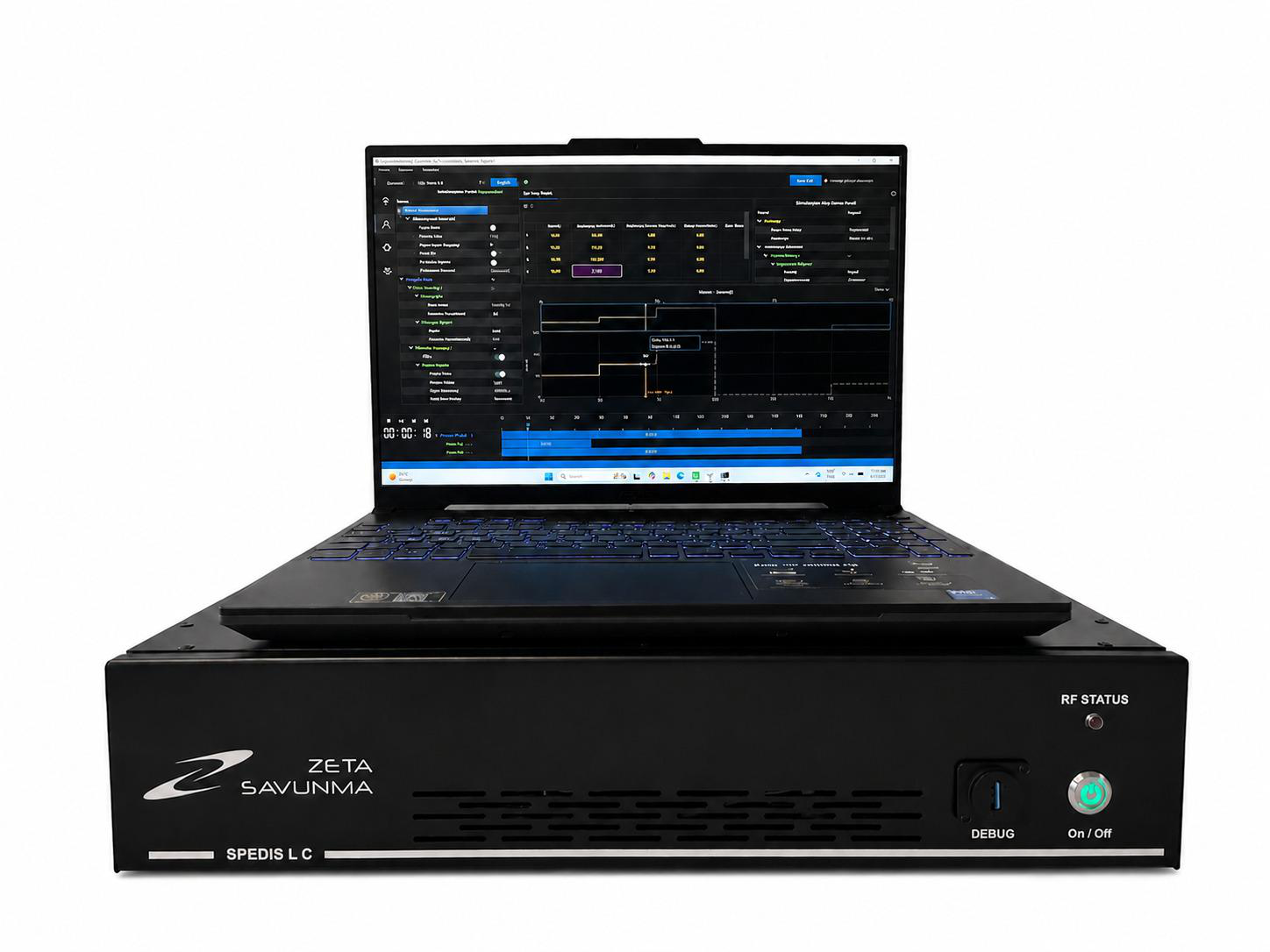
C-band radar altimeter fixed-range echo simulator
SPEDIS L C
1U rack-mounted echo simulator that returns a fixed-range target to a C-band radar altimeter, by direct injection or through antenna coupling units.
- Defence and security
Radar altimeter test system
Tests radar altimeters across their operating range by returning a simulated ground echo that follows the platform's flight profile.
DRFM-based echo simulator that generates the ground return of a radar altimeter for a defined flight profile, for testing on the aircraft, in HWIL and in SIL.
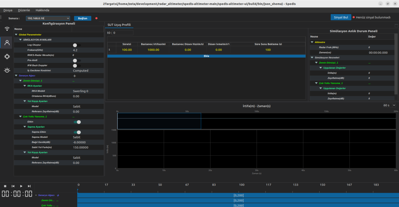
ZETA-RATS tests and verifies radar altimeter systems under different scenarios. The radar altimeter's transmission is received and converted to IF, sampled and processed in DRFM blocks, and returned at the altimeter frequency as a ground echo with the delay and attenuation of the instantaneous altitude in the flight profile. Multipath reflections are added to the same scenario. The system consists of the radar altimeter echo simulator unit, receive and transmit antenna coupling units, a positioning mechanism for the coupling units, automatic test (ATE) software and an operator interface. It is used on the aircraft, in hardware-in-the-loop (HWIL) and in software-in-the-loop (SIL) set-ups, on rotary-wing and fixed-wing platforms.
The simulator returns the altimeter's own FMCW or pulsed signal with the delay of the simulated altitude at 1 m resolution. Ground return uses Swerling 0 to IV radar cross-section models from −60 to +60 dBsm, with a fixed or two-way path loss model.
The flight profile is a sequence of steps with start time, duration, start altitude, vertical velocity, vertical acceleration and hold time. Scenarios are saved, reloaded and played back on a timeline, and instantaneous values are logged every millisecond.
Multipath echoes follow a fixed path difference, a double-bounce model (aircraft to ground and back twice) or random ground points that change during the scenario, with relative amplitude from −40 to −10 dB and path differences from 1 to 5000 m.
A signal detection mode shows the 500 MHz band around the chosen centre frequency, with frequency–time and amplitude–time graphs, max hold, and measured pulse rate, PRI, frequency and amplitude of the altimeter signal.
Receive and transmit antenna coupling units are positioned under the altimeter antennas on tripods and adapted to the fuselage and antenna size. The echo simulator unit is portable and rugged, and the operator tablet connects over Ethernet so that one person runs the test from the cockpit.
Internal delay calibration runs in 100 MHz steps with the RF output looped back to the input, without external test equipment. Built-in test reports the status of the DRFM channels, frequency converters and software services. Test logs, detailed fault reporting and an ATE software interface support fault finding and automated testing.
Detailed specifications and export information are available on request.
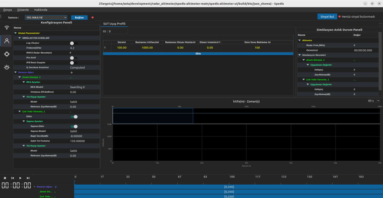
C-band radar altimeter fixed-range echo simulator
1U rack-mounted echo simulator that returns a fixed-range target to a C-band radar altimeter, by direct injection or through antenna coupling units.