
Wideband SDR receiver for signal intelligence
OCR-1911
A 1U wideband software-defined receiver covering 75 MHz to 6 GHz with 200 MHz instantaneous bandwidth and 10 GbE data streaming.
- Defence and security
Aviation band monitoring and recording system
Aviation communications monitoring and interference investigation.
Monitors the 108–138 MHz aviation band around the clock, detects and records transmissions and interference, and brings live audio, detection history and recordings into one operator interface.
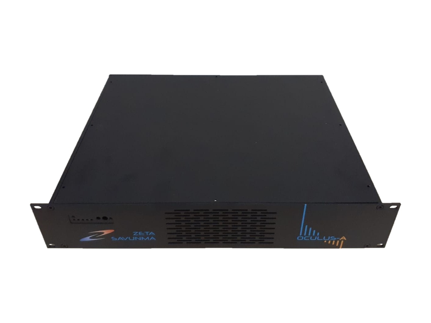
Oculus Airband watches the 108–138 MHz VHF aviation band continuously and records what it receives. Its SDR receiver sees the whole band at once with 30 MHz of instantaneous bandwidth, behind a band-pass filter that keeps out transmissions from outside the band. The recording software detects every signal above the noise floor and channelises several at the same time. Operators define a watch list of the channels they follow, and the system also catches transmissions outside that list, such as FM broadcasts spilling into the band. Spectrum and waterfall views, live AM/FM listening and a searchable detection history support interference investigation, with WAV audio and timestamped RAW records kept for later review. RDS decoding helps identify interfering FM broadcasts, while Morse decoding records three-letter ILS identifiers. The client-server design allows local or remote operation over Gigabit Ethernet.
Operators enter up to 16 frequencies to follow, each with a bandwidth of 10–50 kHz, and mark any of them for Morse decoding. Every other signal that rises above the noise floor by the set SNR threshold, adjustable from 5 to 20 dB, is detected automatically.
The SDR receiver delivers 30 MHz of instantaneous bandwidth with gain adjustable from 0 to 50 dB. FFT-based scanning finds the signals, and multichannel digital down-conversion filters each one to its estimated bandwidth, so up to 32 channels are demodulated and recorded at the same time: 16 from the watch list and 16 detected interference signals.
AM and FM signals are demodulated automatically and saved as compressed WAV files, with centre frequency, bandwidth and SNR stored alongside each one. Timestamped RAW records keep the signal for later analysis. RDS decoding names interfering FM broadcasts, and Morse decoding logs three-letter ILS identifiers.
Operators listen live by selecting a band on the spectrum or by double-clicking a peak, a detection or a point on the waterfall. Squelch keeps noise out of live audio and recordings.
Every detection is listed with start and end time, bandwidth, modulation percentage, SNR and status: live, ended, bandwidth outside the expected value, blacklisted and others. Operators add comments and a two-level threat flag, and the detection filter queries the history by status, signal type and minimum SNR.
The system runs 24/7, with time taken from GPS (UTC) or an NTP server. Disk use is monitored: the operator is warned at 80 %, and above 90 % the oldest records are deleted automatically so recording continues. Server and client run on one computer or apart, over Gigabit Ethernet.
An omnidirectional VHF antenna feeds the first RF input through an aviation-band band-pass filter, which suppresses transmissions outside the aviation band before they reach the receiver. A second RF input serves general-purpose monitoring.
The SDR receiver digitises 30 MHz of instantaneous bandwidth and passes the wideband signal to the recording software.
The recording software detects and channelises the signals, demodulates and decodes them, and writes WAV and RAW records with their parameters to the recording disk.
The operator software connects to the server locally or remotely over Gigabit Ethernet and shows the spectrum, waterfall, detection list and live audio.
Detailed specifications and export information are available on request.
Wideband SDR receiver for signal intelligence
A 1U wideband software-defined receiver covering 75 MHz to 6 GHz with 200 MHz instantaneous bandwidth and 10 GbE data streaming.