Skip to content

Anechoic test cabinets and antenna measurement systems

Anechoic Test Cabinets

Anechoic test cabinets for antenna, array and RF sensor measurements.

Benchtop anechoic cabinets and far-field measurement systems for radiation pattern and calibration measurements of antennas and AESA arrays.

  • Defence and security

Overview

A controlled RF environment on the bench

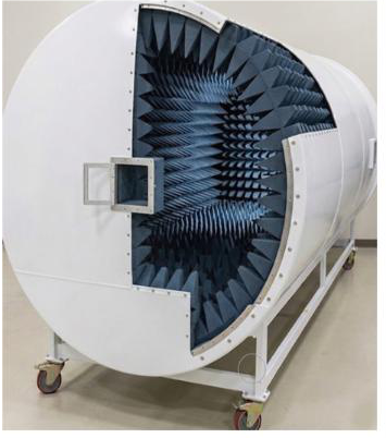
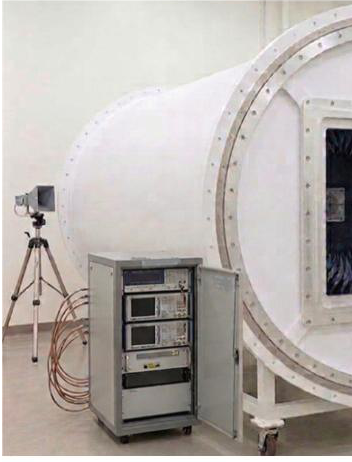
ZETA designs and integrates anechoic test cabinets and the measurement systems inside them. A typical configuration measures AESA antenna prototypes in the far field: the array under test sits on a positioner in the quiet zone, a standard gain horn acts as the probe, and a vector network analyser and control computer measure the 3D radiation pattern and build the calibration map in receive and transmit modes. A benchtop cabinet sized to the array replaces a full-size chamber where space and cost matter.

Key capabilities

  • Cabinet sized to the test item

    01

    Cabinet length, cross-section and absorber height follow from the far-field distance and the lowest test frequency. For an X-band 4 × 8 sub-array this gives a benchtop cabinet of about 2.5 m × 1.2 m × 1.2 m.

  • 3D radiation pattern measurement

    02

    The array is rotated in azimuth and elevation in front of a standard gain horn probe to measure its 3D radiation pattern and beam steering in receive and transmit modes.

  • Channel calibration

    03

    Element-on measurements with a vector network analyser give the amplitude and phase of each channel, from which the array's receive and transmit calibration tables are built.

  • Positioners, horns and absorbers

    04

    Two- or three-axis positioners, standard gain horns for X, Ku and Ka bands and pyramidal absorbers are selected and integrated for the measurement.

Applications

Defence and security

  • Radiation pattern measurement of AESA antenna prototypes
  • Receive and transmit calibration of phased arrays
  • Radiated testing of RF sensors and seekers

Specifications

Bands
X, Ku, Ka
Example cabinet size
About 2.5 m long × 1.2 m wide × 1.2 m high (X-band 4 × 8 sub-array)
Absorber reflectivity
−40 to −50 dB across X band
Positioner
2- or 3-axis, −180° to +180° azimuth and elevation
Maximum test item
300 mm wide, 3 kg (benchtop positioner)
Measurement
Vector network analyser; multi-channel DAC/ADC for digital beamforming

Detailed specifications and export information are available on request.